Building a 1 W solar repeater — Ikoka Stick
By MrAlders0n (Ottawa) · Original guide: January 1, 2026
Build a solar-powered MeshCore repeater using a GOME Ikoka Stick, a junction box enclosure, and an epoxied solar panel.
Board: GOME Ikoka Stick (HW v0.4.0)
Power: Waveshare Solar Power Manager (standard)
Firmware: MeshCore
Before you start
No warranty
This community build guide is provided without a warranty. Check continuity and polarity with a multimeter before applying power. Disconnect solar, battery, and USB power before soldering or changing wiring.
When to use a 1 W repeater
1 W repeaters are useful for backbone links and locations struggling to connect to the mesh. They are not needed at every site; coordinate with your local community.
Antenna required
Attach a LoRa antenna before powering the Ikoka Stick. Transmitting without an antenna can permanently damage the radio. Use the MeshCore power setting for your exact Ikoka radio module; a 1 W output rating is not an instruction to set TX power to 30 dBm.
Parts list
Prices are from the original guide dated January 1, 2026, not current quotes. All amounts are in Canadian dollars; check availability, shipping, and taxes before ordering.
| # | Part | Qty | Price | Source |
|---|---|---|---|---|
| 1 | GOME Ikoka Stick (HW v0.4.0) | 1 | $55 | GitHub (group buy) |
| 2 | Waveshare Solar Power Manager (standard) | 1 | $15 | Waveshare |
| 3 | IP65 Junction Box, 220x170x110mm, Gray | 1 | $30 | AliExpress |
| 4 | Solar panel, 10W/18V, 250x340mm | 1 | $35 | Amazon |
| 5 | 3P1S 18650 battery pack (or 4P1S) | 1 | $25-35 | MP&W Supply |
| 6 | Battery protection board (high/low voltage cutoff) | 1 | $8 | Space Hedgehog |
| 7 | 890-960MHz 4-cavity bandpass filter, 50W (recommended) | 1 | $65 | Alibaba |
| 8 | 10-15cm SMA right angle to N-Type female O-ring nut cable | 1 | $6 | AliExpress |
| 9 | 7.5cm SMA Male 90° to SMA Male 90° cable | 1 | $7 | AliExpress |
| 10 | 0.5ft USB-A to USB-C right angle cable | 1 | $7 | Amazon |
| 11 | M3x35 spacers | 4 | ||
| 12 | M3x5 screws | 8 | ||
| 13 | Gorilla Epoxy Syringe, 25ml | 1 | $15 | Home Depot |
| 14 | Waterproof vent plug (breather valve) | 1 | $2 | AliExpress |
| 15 | Outdoor silicone caulk (clear) | 1 | $10 | Any hardware store |
| 16 | Adafruit INA3221 (optional) | 1 | $15-20 | DigiKey |
Estimated total cost: ~$280-290 without the INA3221, ~$300-310 with it. This does not include the antenna, 3D-printed parts, or mounting hardware (M3 spacers/screws).
Alternative filter option (minimal): Callboost 915MHz cavity filter, 26M BW, $82. AliExpress
Antenna
An antenna is not included in this parts list as selection will vary by deployment. It is highly recommended to use a higher dBi antenna such as a 6-8 dBi or higher with 1W builds. We have found that the Ikoka Stick does not pair well with the Alfa 5.8 dBi antenna for some reason, with several folks in Ottawa observing noticeably worse signal quality when using them together. This is not a definitive statement, just a pattern observed across multiple deployments.
For recommended antenna options, see the GOME Repeater Omni Antennas page.
Tools required
| Tool | Notes |
|---|---|
| Soldering iron | Fine tip recommended for I2C wiring |
| Solder + flux | |
| Multimeter | For continuity and voltage checks |
| Step drill bit | For drilling clean holes in the junction box |
| Jigsaw or rotary tool | For cutting the solar panel opening |
| 1/8" drill bit | For opening up mounting holes |
| Pencil | For marking the cutout |
| Clamps + flat piece of wood | For clamping solar panel during epoxy cure |
| Wire strippers |
Printed parts and downloads
Before starting assembly, you will need the following 3D-printed parts. Both are available for download below:
- Mounting plate for the junction box (holds the filter, Ikoka, and Waveshare board)
-
3P1S 18650 battery holder (or sized to match your chosen battery configuration)
- Mounting plate (.stl)
- 3P1S 18650 battery holder (.stl)
Assembly steps
Keep the solar panel, battery, and USB disconnected while cutting, soldering, or changing wiring.
Enclosure Preparation
-
Flip the solar panel face-down. On the back, locate the black junction box where the red and black power wires exit. Measure this junction box with calipers or a ruler.
-
On the front face of the gray junction box, use a pencil to trace a rectangle matching the solar panel junction box dimensions. Center it near the top of the panel.
-
Using a step drill bit, drill a large starter hole in the center of the traced rectangle.
-
Using a jigsaw or rotary tool, cut along the traced lines to remove the rectangular section. Clean up any rough edges.
Mounting the Solar Panel
-
Mix a batch of Gorilla Epoxy and apply it generously across the entire front face of the junction box, covering the area where the solar panel will sit.
-
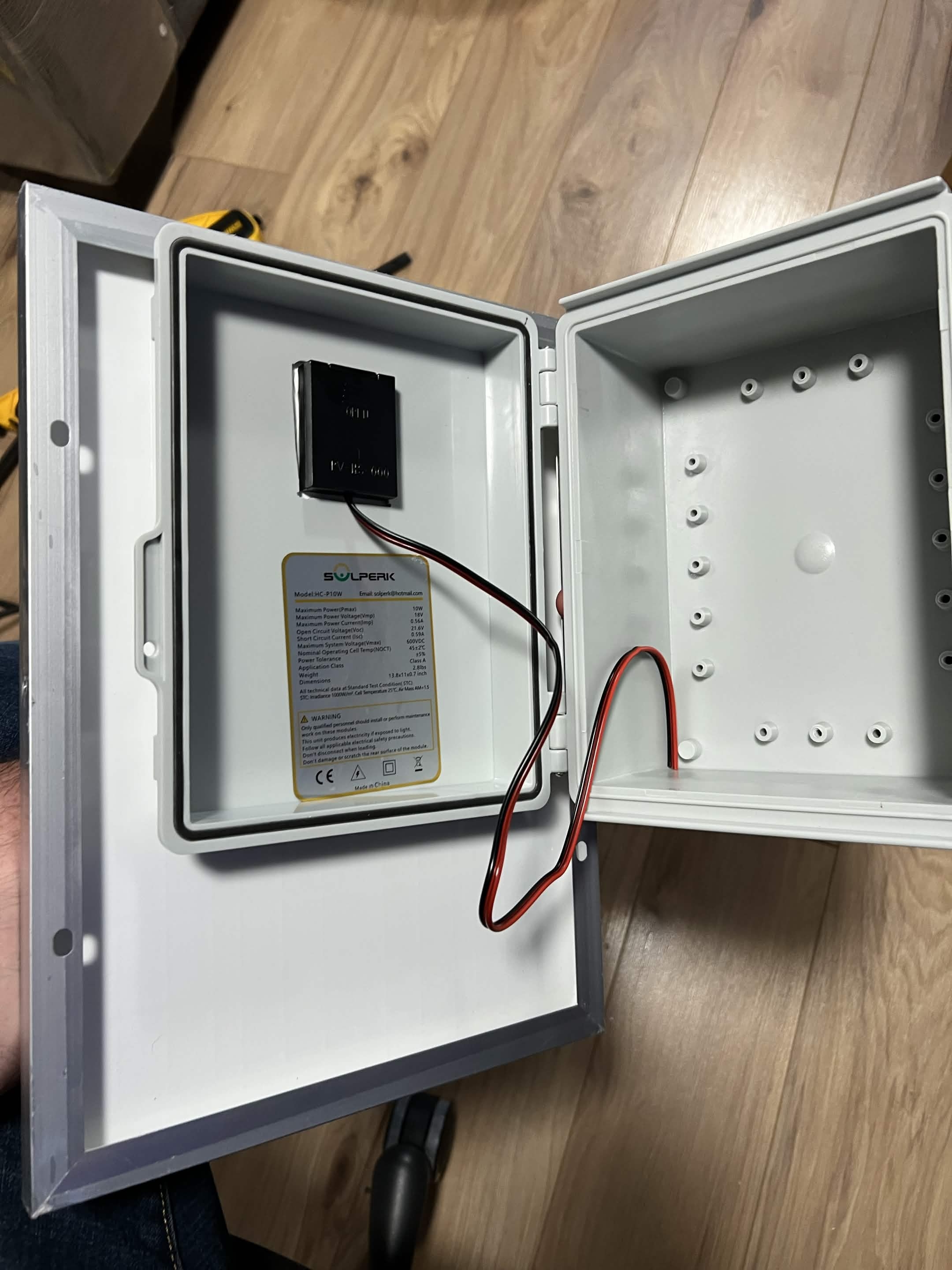
Route the solar panel's power cable through the rectangular cutout from the outside into the box.
-
Press the solar panel onto the epoxied face of the junction box. Place a flat piece of wood across the front of the panel and use clamps on all four corners to apply even pressure. Be careful not to over-tighten, as this can crack the panel. Alternatively, lay the assembly flat on the ground with weights on the back of the box.
-
Allow the epoxy to fully cure according to the manufacturer's instructions before removing the clamps.
-
Using clear outdoor silicone caulk, apply a bead around all four edges where the solar panel meets the junction box. Smooth the caulk to create a weatherproof seal.
Mounting Plate and Filter
-
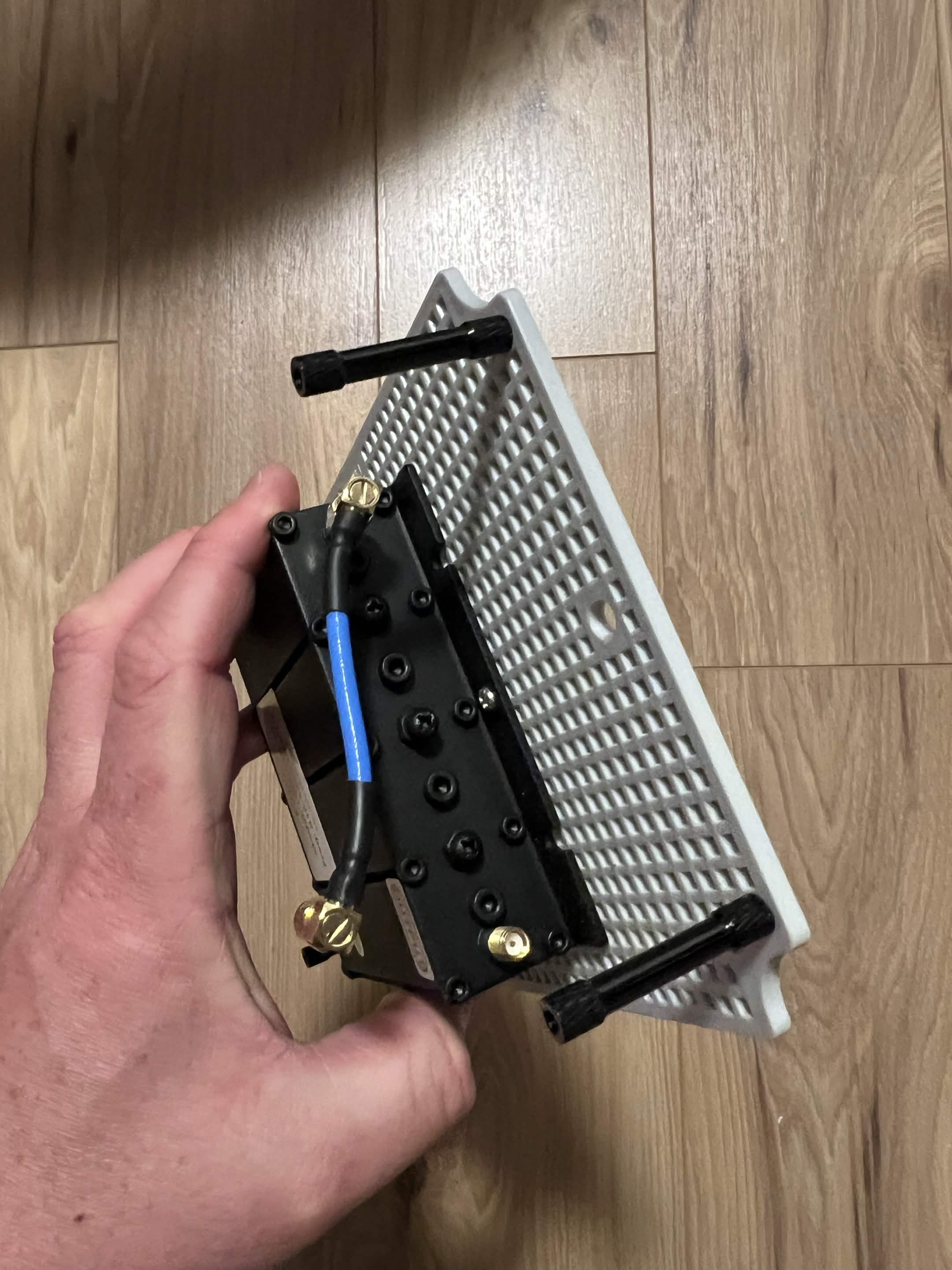
Attach the four M3x35 spacers to the corners of the junction box mounting plate. You may need to use a 1/8" drill bit to open the holes slightly to fit M3 screws through the plate. Use the 3D-printed mount plate as a reference for hole placement.
-
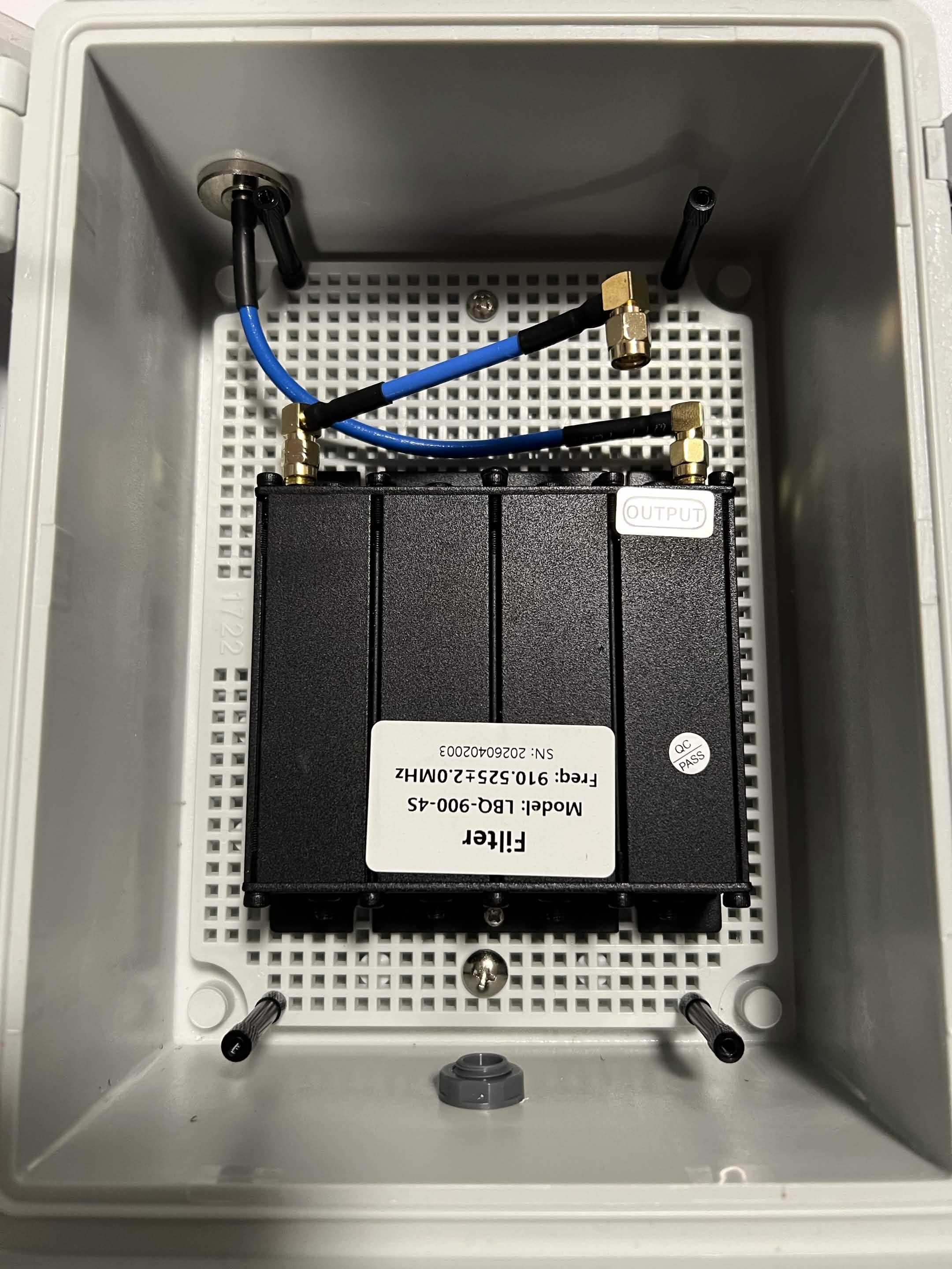
Mount the RF bandpass filter to the mounting plate, positioning it roughly in the center.
-
Connect the N-Type to SMA cable to the filter's output port. This cable will pass through the box wall to the external antenna.
-
Determine where the N-Type connector should exit the junction box. Using a step drill bit, drill the hole, stepping up one size at a time and test-fitting after each step until the connector fits snugly.
-
Feed the N-Type connector through the box wall from the inside out and tighten the O-ring nut to secure it.
-
On the bottom of the junction box, drill a hole for the waterproof vent plug using the step drill bit.
-
Install the vent plug and tighten it.
Filter and Radio Preparation
-
Connect the SMA-to-SMA cable to the filter's input port. Finger-tighten for now.
-
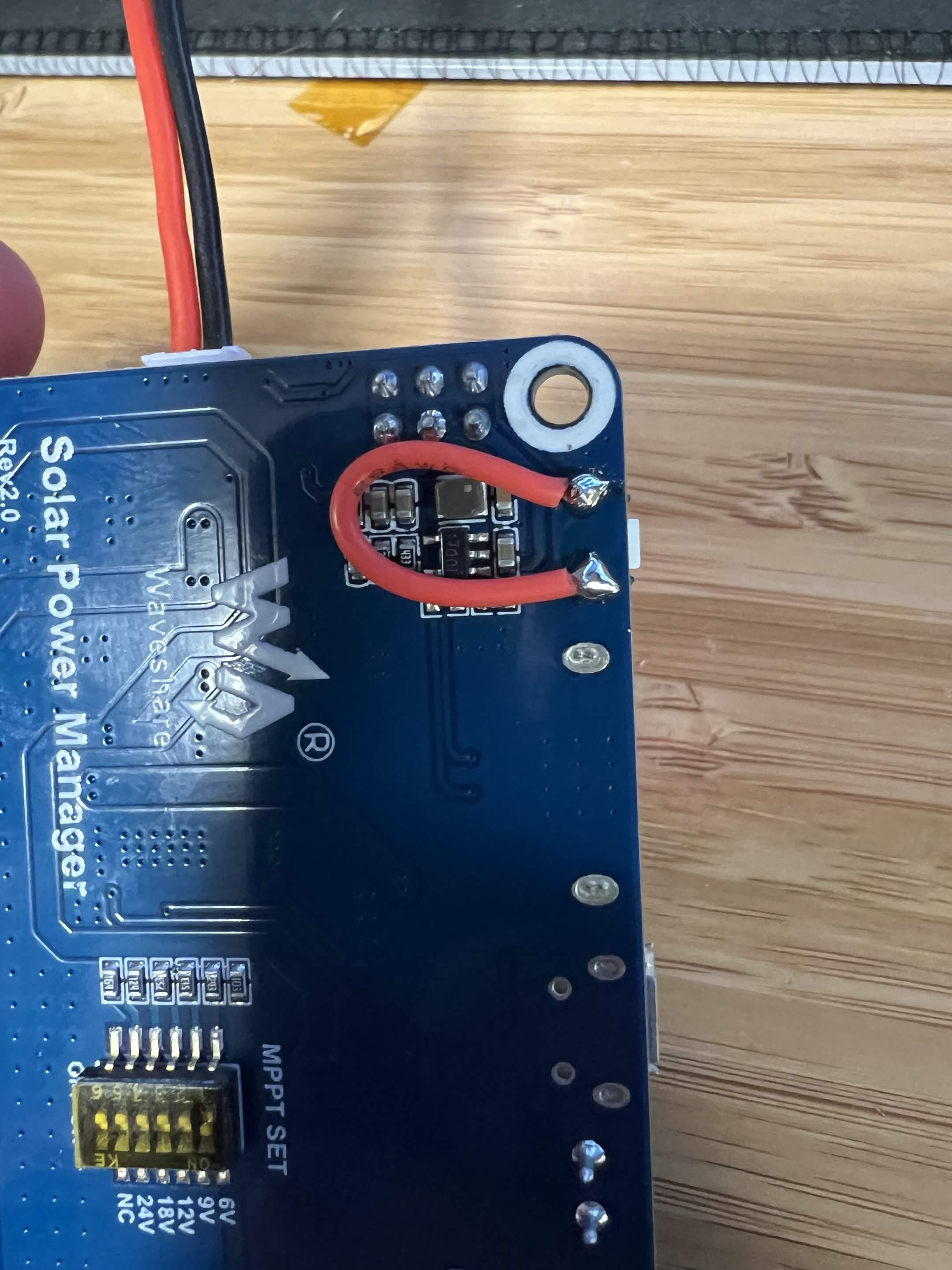
Waveshare Solar Power Manager prep (standard model): The original build uses a wire bridge across the BOOT button pads so that output resumes after a power loss without a button press. With all power disconnected, solder a short wire across the pads on the back of the board, as shown below. This modification is specific to the standard model; do not assume the B, C, or D versions use the same circuit. Test power-loss recovery before sealing the enclosure.
Component Mounting
-
Outside the box (for easier access), mount the Ikoka Stick and the Waveshare Solar Power Manager to the 3D-printed mounting plate. If using the optional INA3221, mount it as well.
-
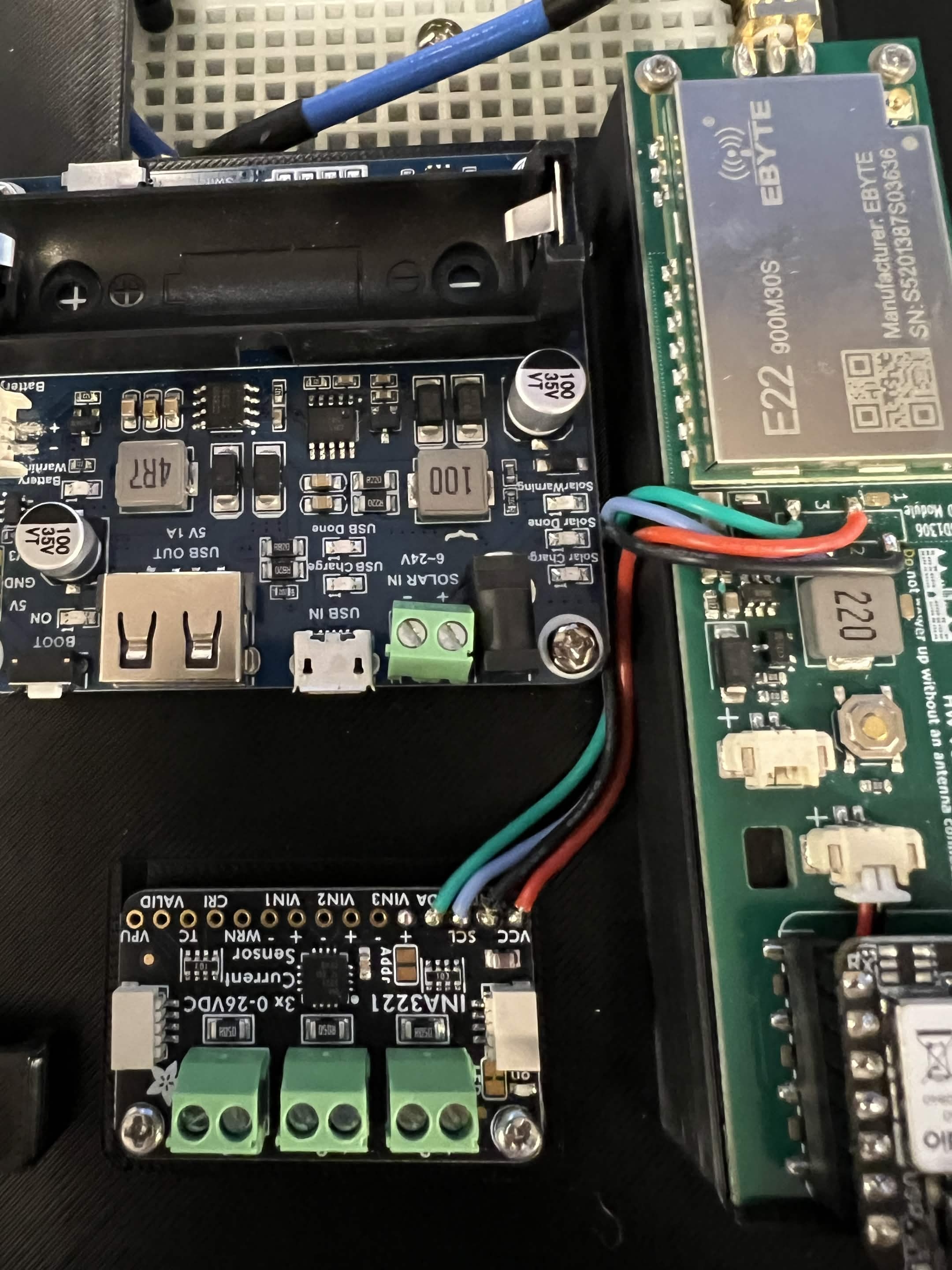
(Optional, Adafruit INA3221) Using a soldering iron, carefully remove the Ikoka Stick's OLED display header pins. Work slowly and gently to avoid damaging nearby components.
-
(Optional, Adafruit INA3221) Solder the INA3221 to the Ikoka's I2C bus using the display header pads. See the INA3221 Wiring section below for the pin connections.
-
Install the mounting plate assembly into the junction box and secure it with M3x5 screws into the M3x35 spacers.
Battery Installation
-
Attach the 3D-printed battery holder to the inside front of the case, below where the solar panel wires enter. Use double-sided tape or epoxy to secure it.
-
If your 18650 battery pack does not have a built-in PCM (protection circuit module), wire the battery protection board between the battery and the Waveshare. Follow the polarity markings carefully.
Power Wiring
-
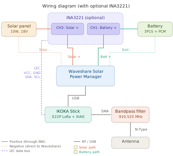
(Optional, Adafruit INA3221) Solar wiring: Connect the solar panel positive wire to INA3221 CH3+. Connect CH3- to the Waveshare solar input positive. Connect the solar panel negative wire directly to the Waveshare solar input negative.
-
(Optional, Adafruit INA3221) Battery wiring: Connect the battery (or the PCM) positive wire to INA3221 CH1+. Connect CH1- to the positive pin on the Waveshare battery JST PH2.0 connector. Connect the battery negative wire directly to the negative pin on the JST PH2.0 connector. Plug the connector into the Waveshare board.
Note: If you are not using the INA3221, wire the solar panel and battery directly to the Waveshare board's solar and battery inputs.
Final Connections
-
Connect the SMA cable from the filter's input to the Ikoka Stick's SMA connector. Snug both ends with a suitable wrench without twisting the cable or overtightening. A loose RF connection will cause signal loss. Attach the external antenna before applying power.
-
Run the USB-A to USB-C cable from the Waveshare Solar Power Manager's USB output to the Ikoka Stick's USB-C input.
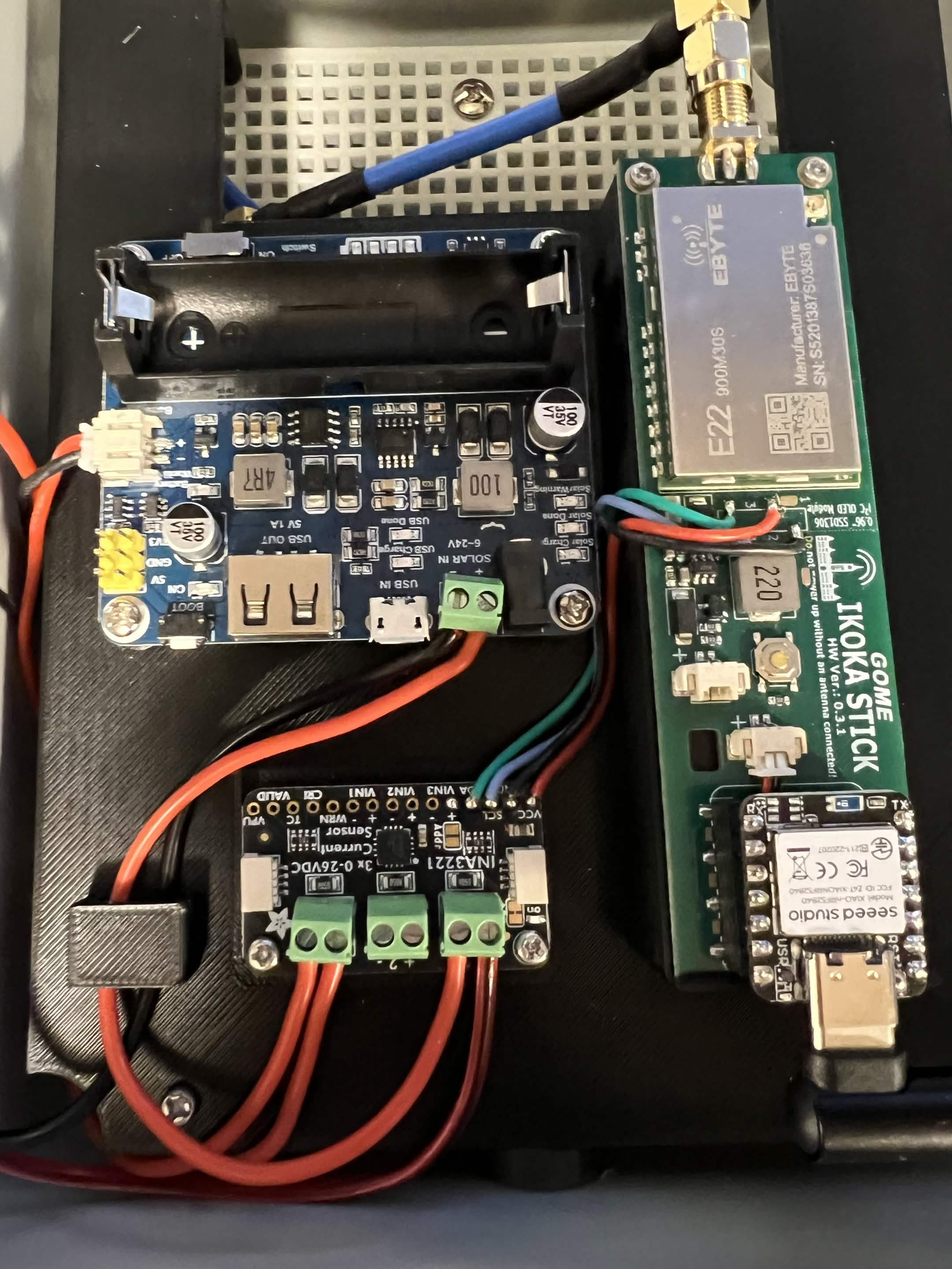
If using the Adafruit INA3221, your completed assembly should look similar to this:
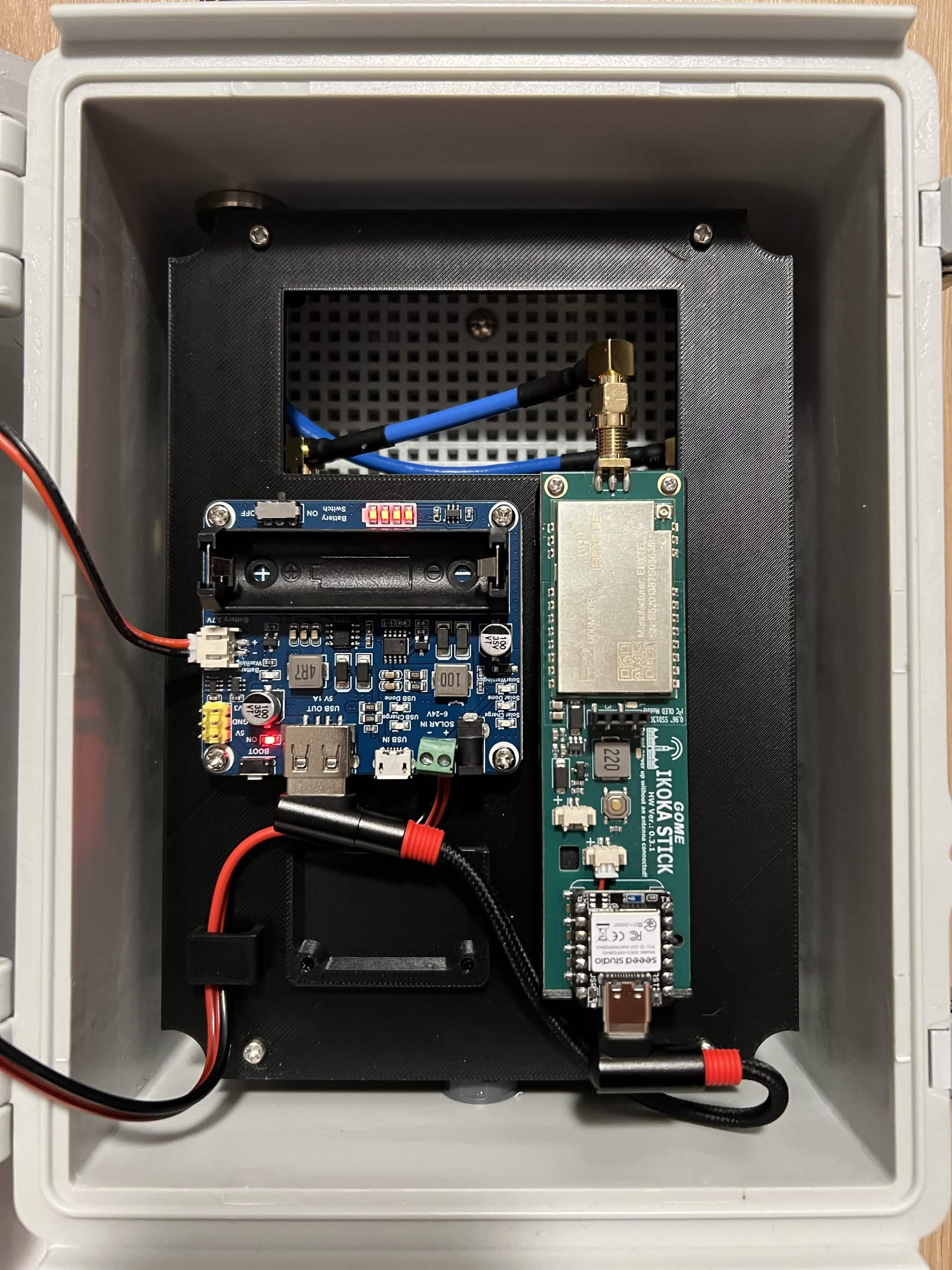
Without the INA3221:
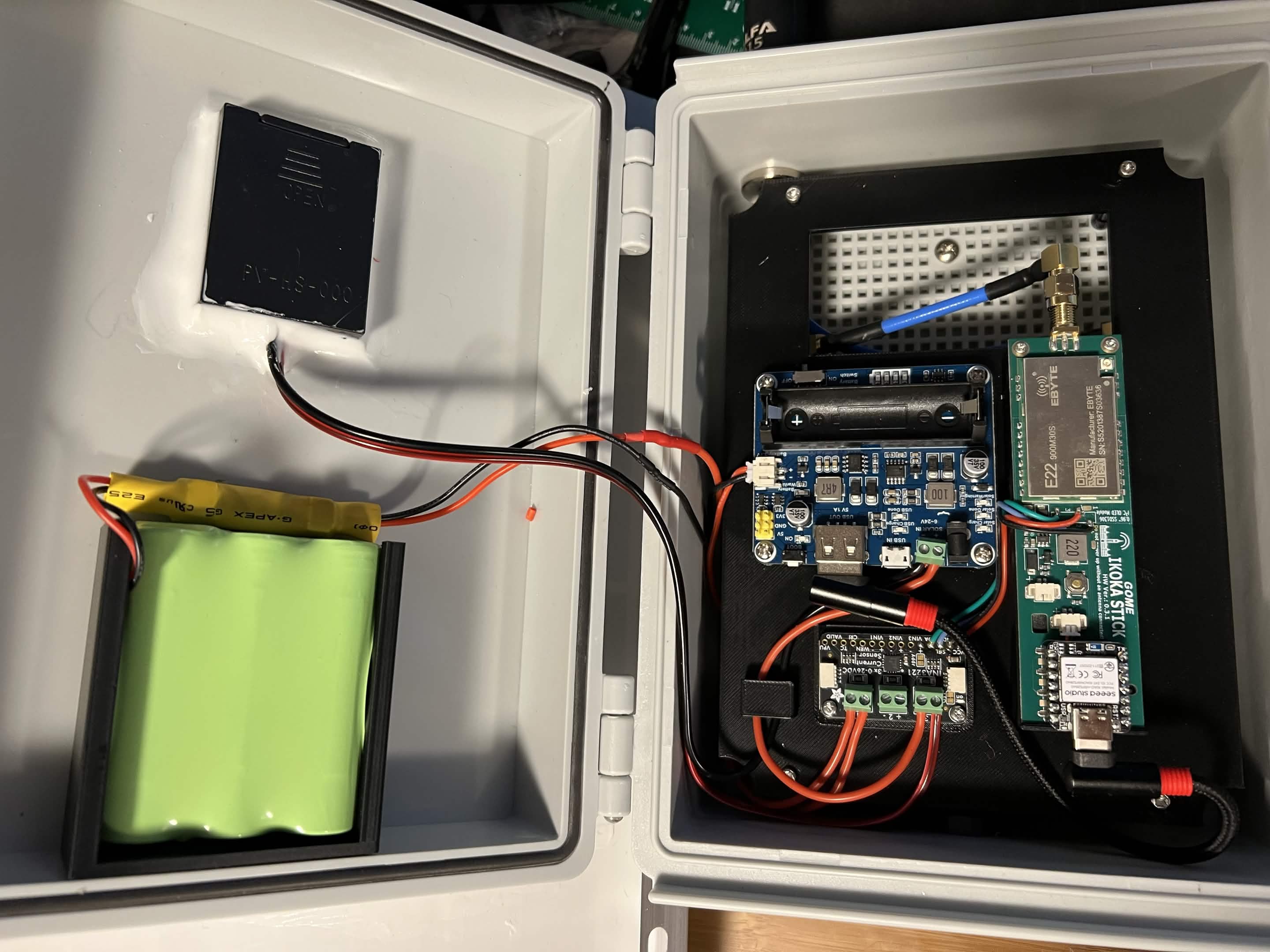
Full interior view with INA3221, battery pack, and all wiring complete:
INA3221 wiring (optional)
The Adafruit INA3221 connects to the Ikoka Stick via I2C using the OLED display header pads. Remove the display header pins and solder wires directly to the pads.
I2C connection (Ikoka display header to INA3221):
| Ikoka Display Header | INA3221 Pin | Wire |
|---|---|---|
| Pin 1 - GND | GND | Ground |
| Pin 2 - VCC (3.3V) | VCC | Power |
| Pin 3 - SCL | SCL | Clock |
| Pin 4 - SDA | SDA | Data |
INA3221 channel assignments:
| Channel | Connected To | Purpose |
|---|---|---|
| CH1 | Battery | Monitor battery voltage and current draw |
| CH2 | (unused) | Available for future use |
| CH3 | Solar | Monitor solar input voltage and charging current |
Note: VCC on the INA3221 is the board power pin (3.3V from the Ikoka). VIN1/VIN2/VIN3 are the measurement channel inputs, not the power pin.
Firmware build flags
MeshCore defaults to address 0x42; the Adafruit INA3221 uses 0x40. Keep the inherited board flags and add the sensor settings to the 30 dBm repeater environment:
[env:ikoka_stick_nrf_30dbm_repeater]
build_flags =
  ${ikoka_stick_nrf_repeater.build_flags}
  ${ikoka_stick_nrf_e22_30dbm.build_flags}
  -D TELEM_INA3221_ADDRESS=0x40
  -UENV_INCLUDE_INA219
  -D TELEM_INA3221_SHUNT_VALUE=0.05
The address and INA219 flags are from the original guide: they select 0x40 and disable the conflicting INA219 driver. The shunt-value flag matches the Adafruit board's 0.05 Ω resistors so current readings use the correct scale. See Adafruit's pinout and MeshCore's sensor defaults.
Wiring diagram
Check before powering on
- Check polarity and continuity, then inspect solder joints for shorts.
- Use a protected, matched 1S battery pack and stay within the cells' charging-temperature limits.
- Confirm the antenna, filter, and RF cables are connected.
- Check that the power manager supplies the expected USB voltage before connecting the radio.
- Test that power returns after an interruption. If fitted, compare INA3221 readings with a multimeter.
- Flash and configure the repeater, then check that a nearby companion receives its advert before installing it.
Troubleshooting and recovery
If the unit does not start, disconnect power and recheck the wiring and BOOT-button modification. Stop using any battery that is hot, swollen, leaking, or damaged. If a firmware change fails, use the USB recovery steps after checking the power and RF connections.
After installation, check the mounting, panel bond, seals, vent, cables, and battery condition regularly and after severe weather.
Source
Restored from MrAlders0n's pre-overhaul guide. The original parts, assembly sequence, photos, wiring tables, and downloads are retained. The optional telemetry example also includes the Adafruit shunt value.
For the standard power manager's limits and connector markings, see the Waveshare manual.